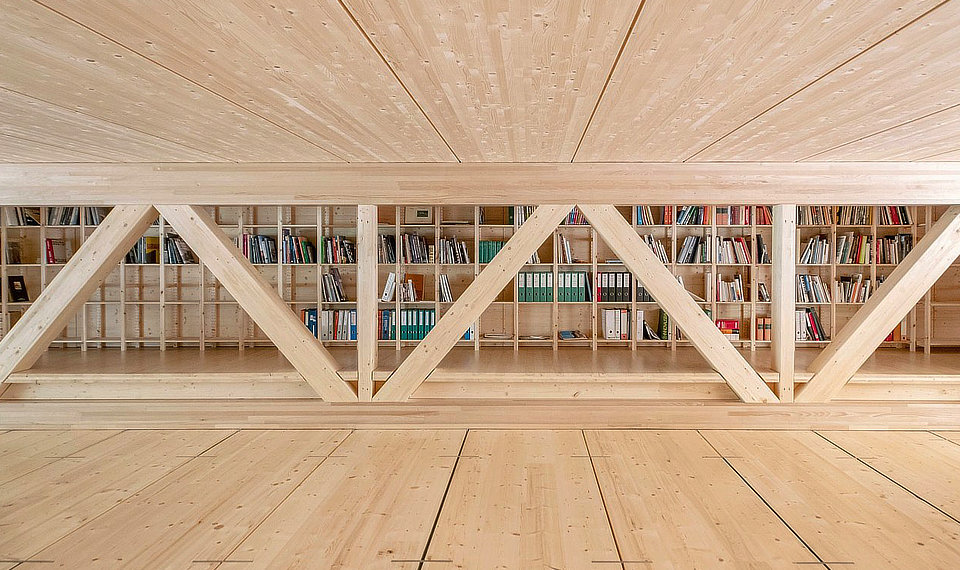
Static plate
There are various possibilities for constructing a static plate: steel strapping, OSB or shear connectors
We will gladly help you with static plate calculations. However, please clarify the following points beforehand:
- design
- horizontal loads to be assumed, such as wind, stabilisation and possibly earthquakes
- type and position of load applications
- position of possible load transfer points, such as walls etc., of the static plate in the floor plan
- bearings, such as sleepers etc., for integration into the concept of the static plate
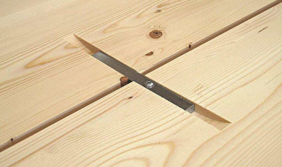
Shear connector
Shear connectors are used to form a static plate with LIGNATUR surface elements. They are also used to align the LIGNATUR elements.
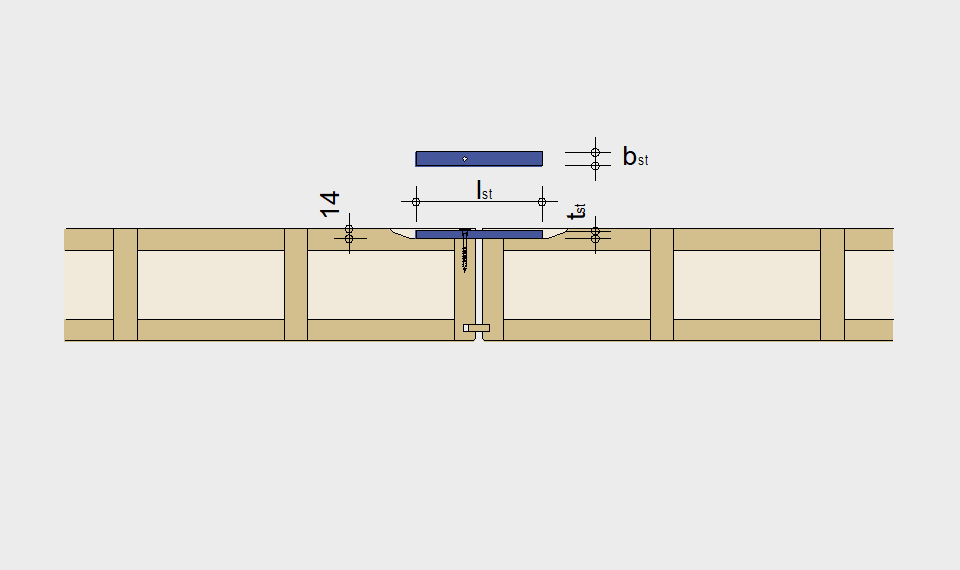
The shear connector is inserted into the factory-prepared groove from above during installation. Fixing with a 6.0 x 60 mm pan head screw into the web serves to secure the position without a static function. The resulting offset torque is transferred via a pair of forces and introduced into the wood via contact. The force transmission therefore functions without constraint and the elements can swell and shrink freely. During installation, at least two shear connectors should be installed per joint before the next element is laid.
Verification with shear connector
Geometry shear connector with steel quality S235
bst: 20 mm
tst: 12 mm
lst: 180 mm
Static characteristics
Characteristic load-carrying capacity shear connector Fv,Rk = 10.19 kN
Shifting module Kser = 4.25 kN/mm
Distance between shear connectors ≥ 32cm
Structural design according to EN 1995-1-1
The modification factor kmod and the partial factor γM change depending on the relevant load case and load duration:
Wind = kmod 0.9; Earthquake = kmod 1.0
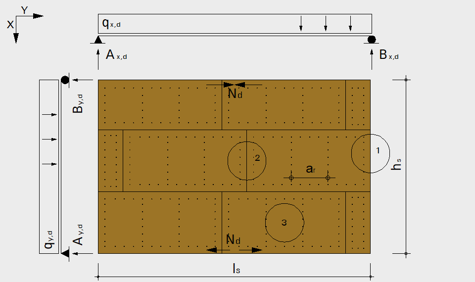
Static system and actions
Geometry:
Length of diaphragm: ls
Width of diaphragm: hs
Actions:
Wind pressure: qDruck,x,d respectively qDruck,y,d
Wind suction: qSog,x,d respectively qSog,y,d
Stabilisation load: qH,x,d respectively qH,y,d
Seismic action: qE,x,d respectively qE,y,d
Pertinent combination wind:
qx,d = qDruck,x,d + qSog,x,d + qH,x,d
qy,d = qDruck,y,d + qH,y,d
Pertinent combination earthquake:
qx,d = qE,x,d + qH,x,d
qy,d = qE,y,d / ls + qH,y,d
Maximum shear force:
Ax,d = Bx,d = qx,d * ls / 2
Ay,d = By,d = qy,d * hs / 2
Maximum moment:
Mz,d = qx,d * ls2 / 8
Maximum compressive / tensile force:
± Nd = Mz,d / hs
± Nd must be taken up by the supports. Joints must be designed with one and a half times the load-carrying capacity! The support reactions Ax,d, Bx,d, Ay,d and By,d must be transmittet through the primary construction.
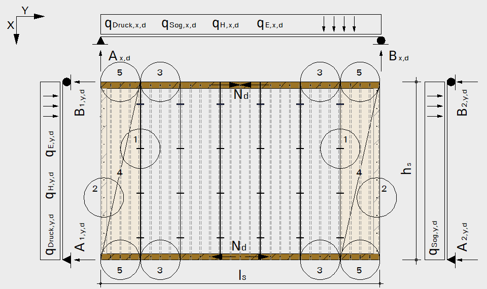
1 Transfer of shear loads
Verification: Ax,d / FRd,tot ≤ 1.00
Ax,d Maximum shear force
FRd,tot Total design load-carrying capacity
FRd,tot = FRd * n
n Number of shear connectors
FRd Design load-carrying capacity per shear connector
FRd = FRk * kmod / γM
FRk Characteristic load-carrying capacity per shear connector = 10.19 kN
kmod Modification factor according to EN 1995-1-1 depending on the relevant load case or load duration
γM Partial factor
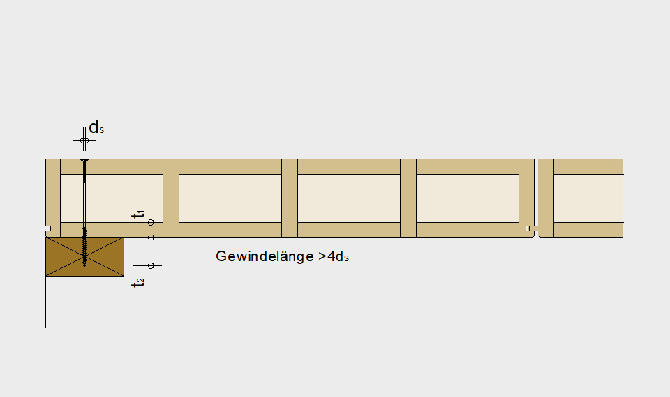
2 Connection to the supports
Verification: Ax,d / Fv,Rd,tot ≤ 1.00
Ax,d Maximum shear force
Fv,Rd,tot Total design load-carrying capacity
Fv,Rd,tot = Fv,Rd * n
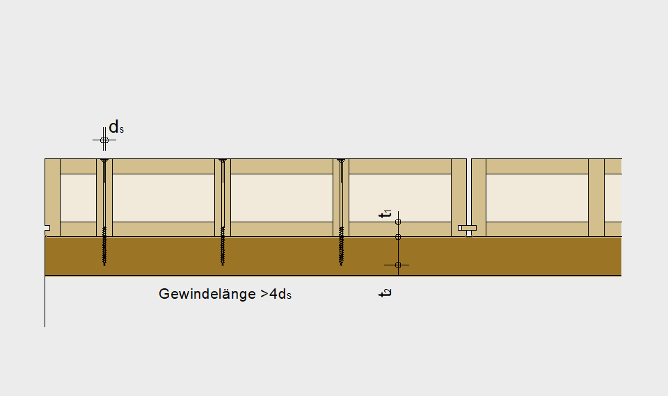
n Number of screws per row, SPAX Senkkopf, screw diameter dS = 8 mm
Fv,Rd Design load-carrying capacity per screw
Fv,Rd = Fv,Rk * kmod / γM
Fv,Rk Characteristic load-carrying capacity per screw = 3.00 kN (pre-drilled)
at:
t1 Wood thickness (element) = 31 mm
t2 Penetration in the support = 40 mm
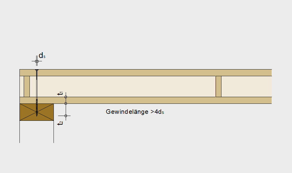
3 Connection parallel to the longitudinal wall
Verification: Ed / Fv,Rd,tot ≤ 1.00
Ed Maximum action parallel to the longitudinal wall
Fv,Rd,tot Total design load-carrying capacity
Ed = √(sw,v,d2 +qDruck,x,d2 ) / 1.00m
sw,v,d = Ax,d / hs
sw,v,d shear flow
qx,d Maximum shear force
Fv,Rd,tot = Fv,Rd * n
n Numbers of screws per row per m, SPAX Senkkopf, screw diameter dS = 8 mm
Fv,Rd Design load-carrying capacity per screw
Fv,Rd = Fv,Rk * kmod / γM
Fv,Rk Characteristic load-carrying capacity per screw = 3.00 kN (pre-drilled)
at:
t1 Wood thickness (element) = 31 mm
t2 Penetration in the support = 40 mm
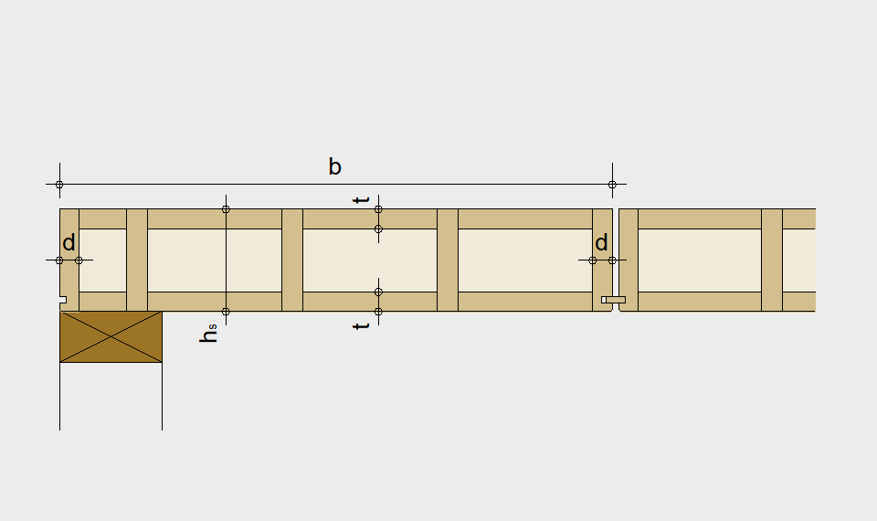
4 Verification of the load-carrying capacity
Verification: σm,d / fm,d ≤ 1.00
σm,d Maximum bending stress
fm,d Design bending strength
Verification: τd / fv,d ≤ 1.00
τd Maximum shear stress
fv,d Design shear strength
Maximum horizontal bending: wy ≥ hs / 1000
at:
b Element width
hs Element height
t Slat thickness
d Web thickness = 31 mm
5 Connection of border elements to the supports
Verification: Ay,d / Fv,Rd,tot ≤ 1.00
Ay,d Maximum shear force
Fv,Rd,tot Total design load-carrying capacity
Fv,Rd,tot = Fv,Rd * n
n Number of screws per row, SPAX Senkkopf, screw diameter dS = 8 mm
Fv,Rd Design load-carrying capacity per screw
Fv,Rd = Fv,Rk * kmod / γM
Fv,Rk Characteristic load-carrying capacity per screw = 3.00 kN (pre-drilled)
at:
t1 Wood thickness (element) = 31 mm
t2 Penetration in the support = 40 mm
Static plate
Dimensioning values
moment
Mz,d (qx,d) = qx,d . ls 2 / 8
tensile / compressive force
Zd = Nd = Mz,d / hs
shear force / bearing reaction
Ax,d = Bx,d = qx,d . ls / 2
Ay,d = By,d = qy,d . hs / 2
flow of shear forces
sv,0,d = Ax,d / hs
Verification
1 fasteners
fv,0,d = kv1 . Rd / av ≥ sv,0,d
2 shear strength OSB
fv,0,d = kv1 . kv2 . fv,d . t ≥ sv,0,d
3 shear buckling OSB
fv,0,d = kv1 . kv2 . fv,d . 35 . t² / ar ≥ sv,0,d
kv1 = 1.0 (boards are rigidly connected all around)
kv2 = 0.33 (one-sided sheating)
av = distance fasteners
t = 15 mm (thickness OSB)
ar = 800 mm (distance studs)
Rd,staple,Ø1.8 mm = 0.52 kN
kmod = 0.9
The floor bearings need to be dimensioned so that they can take the loads from Nd and Zd and transfer the reactions from the static plate. The design is performed according to EN 1995-1-1, section 9.2.3.